Photo Booth (Part 4): Wiring up the Circuit
( and adding the LED lights )
Overview of Part 4
Part 4 describes:
- The steps I took in attaching a 12v LED strip to my photo booth.
- How to wire the photo booth
Tools and Materials
We will need the following parts and tools (in addition to the photo booth cabinet that we built earlier):
Required Parts
- LED strip lights
- I am using (warm) white colour LEDS.
- If you are using RGB LEDs (i.e. capable of multiple colours) this will require more complex installation
- Power supply for the strip lights
(needs to to supply 12 volt and support up to 2 amps) - Hookup wire
- Heat shrink tubing
Required Tools
- Drill
- Soldering iron (and Solder)
- Side cutters or Scissors
- Wire strippers
Optional Parts/Tools
- Multimeter
- Alligator clips / wires
- Pair of barrel connectors (these came with my lights, but are optional.
- Helping hands
- Wood clamps
- Wood glue
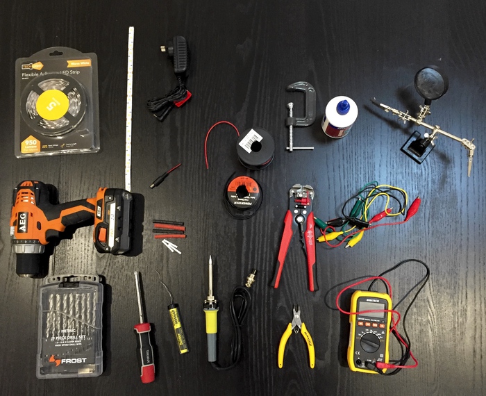
The Lights
Intro to LED strips
If you have never worked with LED strip lights before, they are really quite an interesting component. The LED strips come in various flavours (RGB or White; Waterproof or Otherwise; …etc.), densities, levels of brightness, and levels of quality.
Common to all LED strips are dotted line markings which will occur at various intervals, indicating where you are able to cut the strip. You must only cut the strip along the dotted lines.
Measure the width of the photo booth, and cut the strip at the appropriate length.
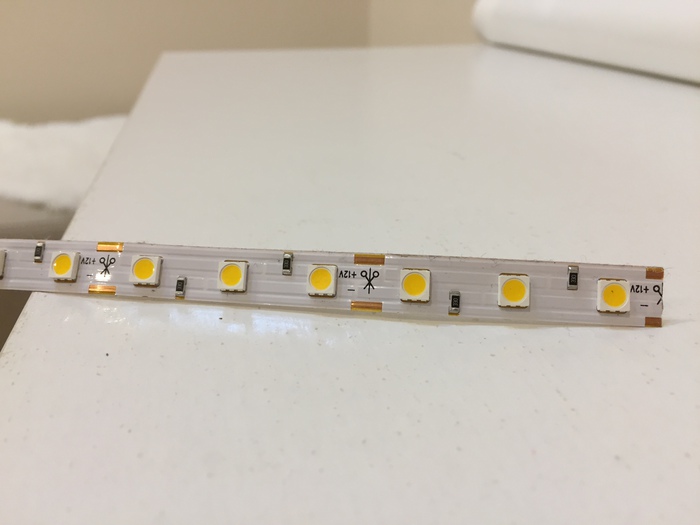
Checking the electrical resistance of the LED strip
LEDs have a very low resistance - and as a rule, you should never connect an LED directly to a power supply without the inclusion of a resistor within the circuit.
However - most LED strips will already include the necessary resistors as part of the strip, which means you don’t have to worry.
We can check for the presence of such resistors by attaching the LEDs to a multimeter in resistance mode (Ω).
A quick LED test
You should always get in the habit of testing your circuits early.
In this case, we should test that our LED strip lights up when connected to power. This will also allow you to determine the lights’ brightness, which may influence your design.
If your lights don’t illuminate, check that you have the +ve and -ve connected to the correct terminals.
Preparing the mounting position for the lights
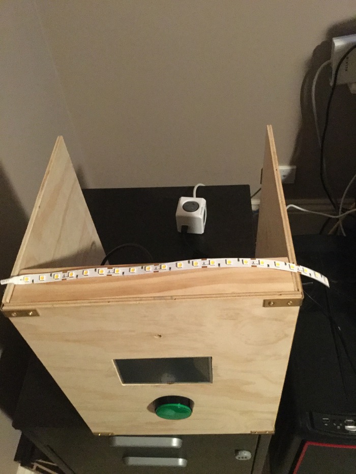
Based on the brightness of my lights, I was keen to ensure that the LED Lights would deflect off my wooden “flash diffuser” rather than being pointed directly at the user of the photo booth.
Regardless of your decision in this regard, you will need to drill a hole that will allow your hookup wires to connect up with the rest of the circuit.
Attaching some hookup wires
Attach some hookup wires to your LED strip. For obvious reasons, you want to attach these hookup wires before the LEDs are mounted on the booth.
I’ve used a barrel connector, as this means I can easily detach and re-attach the lights from the rest of the circuit. We don’t want to solder directly to the power supply yet, as this will make it hard to
When soldering:
- Give your iron a few minutes to heat up to temperature.
- A “helping hands” tool might make it easier to keep your components under control.
- Using different colour wires will make it easier to remember which terminal is positive, and which is negative.
Mounting the LEDs to the booth
This step should be relatively simple.
- Decide upon the exact position for the lights
- Ensure that the hookup wires are able to pass through the hole that we drilled earlier.
- Remove the sticky adhesive from the back of the light strip, and attach to the booth.
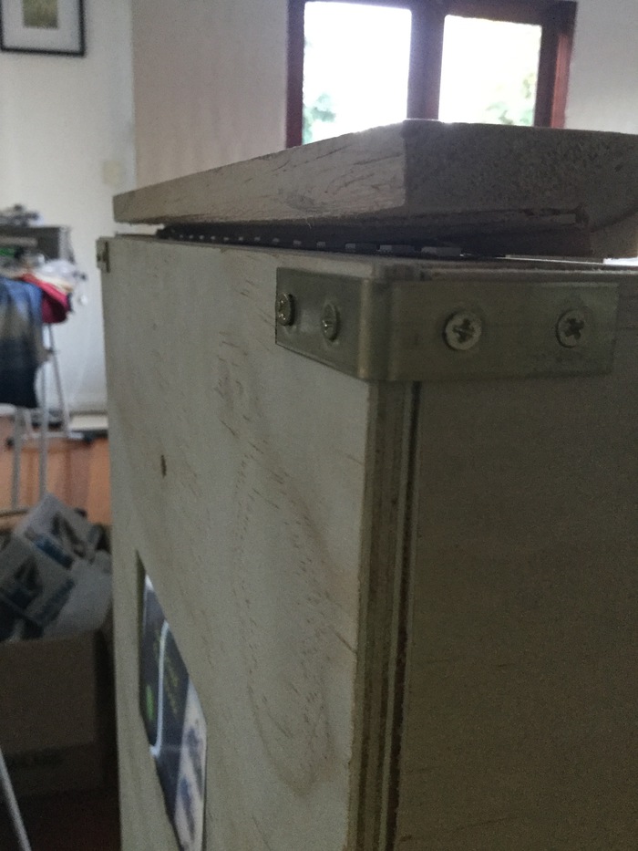
My light strip refused to stay flat against the booth, particularly where the hookup wires were attached. I fixed this with some wood glue, and clamping the stubborn section until the glue dried.
Wiring the Booth
Version 1: The “Power Board Method”
For the first version, I relied on multiple power adapters to provide each of the different voltages required by the circuit.
Note that (in my photo booth) the LEDs in both the arcade button & and LED strip include resistors which allow them to safely operate at 12v (your parts may vary).
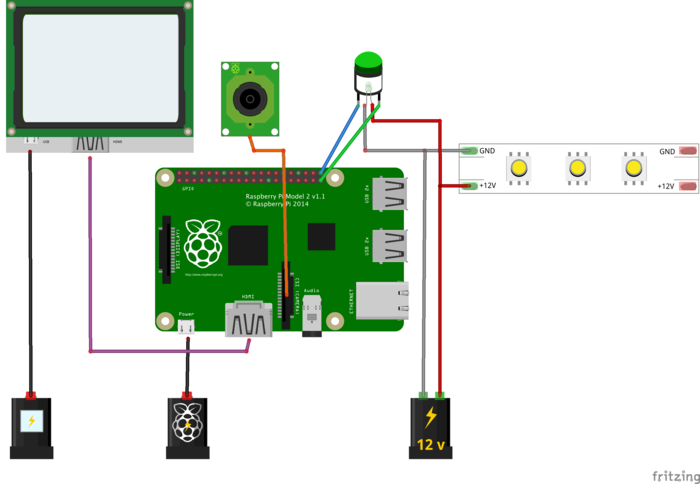
Rigged up in the wooden cabinet, the circuit looks like this:
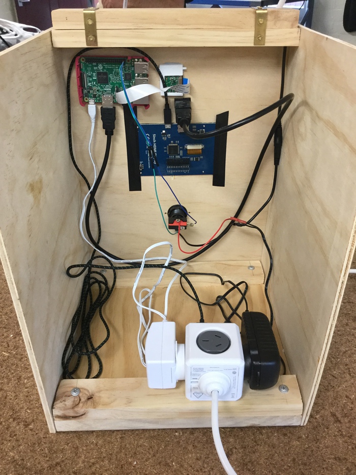
Version 2: A Single Power Source
The circuit design can be improved so as to include only one power source.
In a future post I intend to document this further.
Next article
For the next article in this series, I’ll be talking about writing the code that will run on our photo booth.
Subscribe to my blog to stay informed of my progress.