Photo Booth (Part 2): Getting started with Pi and PiCamera
Breadboarders, assemble!
Overview of Part 2
Before providing a full set of components and plans for the Photo Booth, I’d recommend breadboarding out a simple version to get you started.
If you want to skip that step, then feel free to jump ahead.
Getting Started with Pi and PiCamera
To start breadboarding out the photo booth, you will need:
- A Raspberry Pi
- I am using version 3 of the Raspberry Pi
- I have also tested my code against;
- Pi version 4 (works fine)
- Pi version 2B (works fine)
- Pi zero (works fine)
- An SD card
- I am using a 16Gb card, smaller cards will also work.
- A Pi Camera
- I am using PiCamera version 2
- The earlier version of the camera will also be fine (although fewer megapixels)
- The Pi “High Quality” camera will also work.
- For a photo booth using the HQ camera, you should use the 6mm (wide angle) lens.
- It might be tempting to use the 16mm (Telephoto) lens, but your photos will be “too zoomed in” to photograph a group of people.
- An LCD screen, such as: the XPT2046
To power the screen, you will also need:- a spare USB phone charger, and
- a spare micro USB cable
- Jumper wires
- Get a mix of M-M, M-F, and F-F
- A momentary push button
- Later on in the project, we will use a large arcade button w/ LED
- If you don’t have this right now, then you can proceed with a simple momentary switch button, or by just connecting and disconnecting a wire within the circuit
- A breadboard
- A keyboard you can borrow, and connect up to the Pi.
- Optional materials:
- A raspberry Pi breakout breadboard
(you will see that I was using this in a couple of the images below; but, for this project it’s overkill and really not required)
- A raspberry Pi breakout breadboard
Preparing your Pi
Installing the Operating System
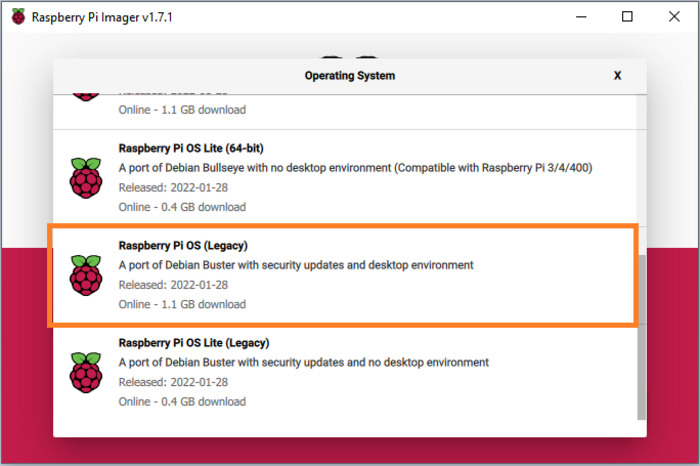
For prototyping, I am running:
Currently, we cannot use the latest version of Pi OS. This is because a number of changes were made to the handling of cameras in the latest version of Pi OS (Bullseye). In future, I will update my code to work with the latest Pi OS, once the relevant Python code libraries (i.e. PiCamera2) are available.**
To install the Pi OS onto an SD card, you will need to download the Raspberry Pi Imager
For additional support in flashing Pi OS to an SD card, refer: Pi Software Guide that will help you in completing this step.
Alternatives
Using Raspian, the boot time for the Photo Booth is roughly 40 seconds, and (for me) I was content enough with this duration that I haven’t looked too far into alternatives at this stage.
If you want the booth to boot faster, then you may want to look at running a more light-weight OS. This is not a topic that I intend to cover right now, but I may cover this later after testing a few different options out.
Raspberry Pi Configuration
If you haven’t already done so, make sure you’ve got a keyboard and mouse plugged in to your Pi, and that the Pi is hooked up to a screen (which can even be the photo booth’s LCD screen if you like).
We are going need to change a number of configuration options, in order to get the most out of out Pi.
You can do this via the Raspbian application menu, selecting: Preferences > Raspberry Pi Configuration.
Alternatively, you can access a similar set of options via the command line (using sudo raspi-config).
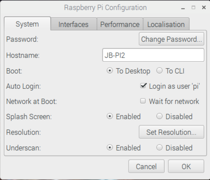
- Within System;
- Make sure you click
Change password
(Even though “it’s only a Pi”, it’s never a good idea to keep using the default passwordraspberry).
- Make sure you click
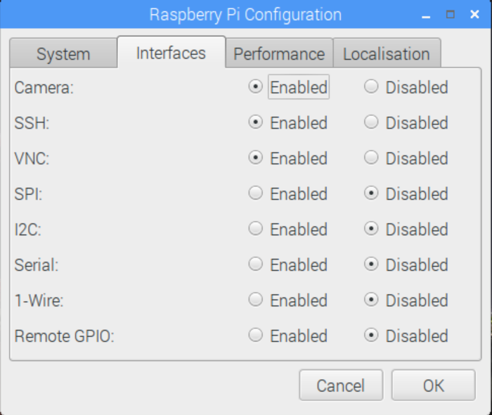
- Within Interfaces;
- You must enable ‘Camera’.
- Other useful options to enable here are:
- ‘VNC’, which lets you remotely connect to the Pi from another computer (after downloading the RealVNC Viewer client application, onto another computer).
- ‘SSH’, which allows you to connect remotely to the pi via an SSH terminal. This is an option for advanced users, and not required for this tutorial.
- Within Localisation;
- By default, your Pi is probably configured to use a UK Keyboard.
- If your keyboard doesn’t have a pound key (£) on it, then you probably need to switch to a US keyboard (or whichever keyboard is appropriate to you).
- It’s also worth changing your Locale, Timezone, and WiFi country while here.
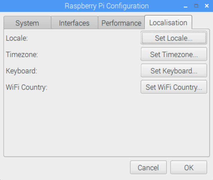
Click OK, to save.
After saving all of these options, you should restart the Pi to ensure that the changes take effect.
Connecting to WiFi
If you haven’t already done so, you’ll now want to connect your Pi to WiFi.
If you are using Raspbian this is relatively straightforward (just click the wireless networking logo in the top right of the screen, and setup the network).
Once you’ve connected up to WiFi, it is also possible to connect to the Pi from another computer via VNC or SSH. We’ll get to this step later on.
Connecting the LCD Screen
If you haven’t already done so, connect the Pi to the LCD screen that we will be using as the screen for the Photo Booth.
My screen connected to the Pi via an HDMI cable.
The screen also requires a separate power source (until I get around to tidying that up). The easiest way to do this is a via a spare USB phone charger and micro-USB cable.
When I first connected the screen, the display settings weren’t 100% correct, but we can fix that now.
Open up the Terminal, we are going to enter the following command:
sudo nano /boot/config.txt
#Note: You will be prompted to enter your password
We can then edit the config file, and we’ll need to add the following lines of code to the end of the file;
hdmi_force_hotplug=1
start_x=1
disable_camera_led=1
gpu_mem=128
hdmi_group=2
hdmi_mode=87
hdmi_cvt=800 480 60 6 0 0 0
The impact of these changes is as follows;
- hdmi_force_hotplug=1
- This forces the Pi to use HDMI mode, even if an HDMI cable is not detected.
- start_x=1
- This enables the camera module.
- disable_camera_led=1
- This disables the camera LED, which usually comes on when the camera is in use.
- gpu_mem=128
- This allocates us some memory to use the camera.
- hdmi_group=2
- This allows us to use DMT display formats.
- hdmi_mode=87
- This allows us to specify custom display settings.
- hdmi_cvt=800 480 60 6 0 0 0
- These are the display settings for our screen: (i.e. 800x480 pixels, 60Hz, 15:9 ratio, no margins, progressive interlace, normal)
To exit the file press CTRL + X; and then specifying Y to save changes.
After making these changes, you should reboot the Pi.
If you’ve made a mistake whilst changing any of these settings, you can boot the Pi in recovery mode (hold the right SHIFT key), and then edit the config file (e).
Connecting the Camera
If you’ve gone with a PiCamera per my recommendation then installation is straight-forward (although perhaps a bit fiddly). The camera will connect to your Pi via a Ribbon Connector.
I’d recommend looking up a YouTube video for how to connect your Pi to the camera. It is different for each version of the Pi, and the latch mechanisms can be a bit fragile if forced in the wrong manner.
A Test Run of the Camera
Connecting to the Pi from another computer
Because we will be using the LCD screen to display the camera’s output, and we still want to be able to enter commands at the same time, it is best to connect to the Pi from another computer (using VNC Viewer or SSH).
The easier option for beginners is using the VNC Viewer. There are instructions to help you do this, here.
Once we are connected to the Pi remotely, we can familiarise ourselves with the PyCamera library.
Begin by opening Terminal or UXTerm on the Pi. You will be greeted with a command prompt.
From here, we can access the python interpreter by typing python.
Camera test via Python interpreter
Within the interpreter, enter the following commands:
import picamera
camera = picamera.PiCamera()
camera.start_preview()
The camera will now be displaying your picture on the screen that is connected to the Pi.
(Note, if you ignored my suggestion to connect to the Pi from another computer, you can close the app by typing ctrl + \).
Flip and Rotate the camera
You may need to flip and/or rotate the picture, such that it suits the angle your camera has been mounted at.
camera.hflip = True
camera.rotation = 90
Save a photo
Enter a couple more commands into the terminal, to save a photo:
filename = '~\my_test_photo.jpg'
camera.capture(filename)
Exit the python interpreter:
exit()You can now see that the photo has been saved to the Pi.
ls ~Connecting up the button
Now that we have a basic understanding of how our PiCamera will work, it is time to connect our button.
Shutdown the Pi:
sudo shutdown nowDisconnect the power supply.
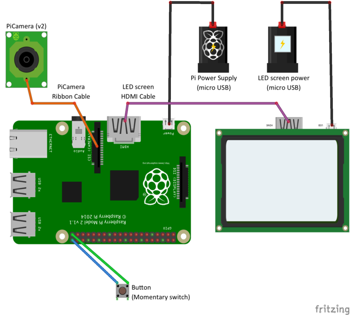
The button needs to connect to GPIO21 and Ground.
Once the button is attached we can safely boot up the Pi again.
Connect your button to the Pi, as follows:
Running a “Test app”
Once the button is connected we can run a simplified version of our photo booth code.
This piece of code doesn’t have the full functionality of my finished photo booth, but it contains “just enough” to test out the functionality that we care about and get an idea of how the finished code might look.
The code we are going to run is shown here:
Boot up your Raspberry Pi again.
You can then either;
- Copy the code into a text file (
simple-photo-booth.py) manually, or - Enter the following at the command line on the Pi to download it:
mkdir ~/simple-photo-booth
git clone https://gist.github.com/8105081adfc0d6dd7da77cd813c69593.git ~/simple-photo-booth
Run the code via:
cd ~/simple-photo-booth
python simple-photo-booth.py
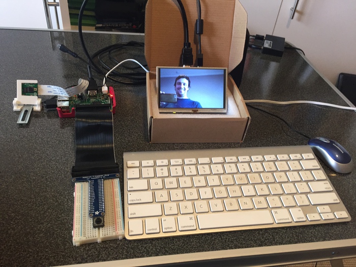
Press the button to test the code.
To exit the simple photo booth app, press ctrl + c.
Next article
For the next article in this series, I’ll be talking about building the wood cabinet that houses the photo booth.
If you’d prefer to skip that step, you can jump ahead to Part 5, where we extend our “simple photo booth” code into a Fully-featured Photo Booth app.