Photo Booth (Part 3): Building the Booth
(♫) If I were a Carpenter...
Overview of Part 3
Part 3 describes the steps I took in making the wooden cabinet for my Photo Booth.
If you already have a cabinet for you photo booth (perhaps a converted wooden winebox?), then feel free to skip ahead to the next post. Otherwise, read on.
I should probably also caveat this post with the fact that I am not a master carpenter. That said, it’s a skill I am presently looking to develop. I may have more updates to this post in future.
I should also note that the cabinet I made was quite large (far larger than is necessitated by the electronic components). I chose to build the photo booth at this size, because I wanted people to see it and interact with it.
Tools and Materials
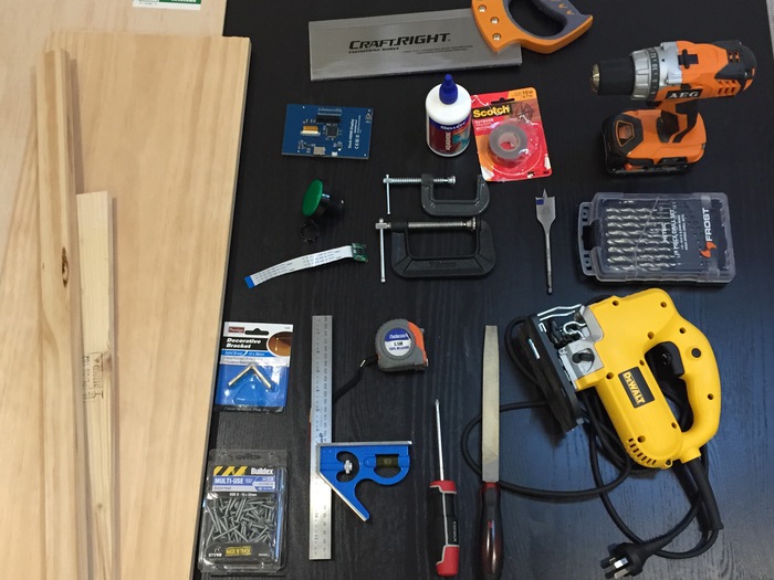
Required Materials
- We need all of the following parts (discussed previously) on hand, because we’ll have to cut holes in the cabinet for each:
- LED screen,
- Arcade button,
- The PiCamera.
- Wood;
more specifically, I used:- A hard plywood for the base
- Some additional plywood for support struts
- A thin plywood laminate for the sides
- Note that My photo booth doesn’t have a lid or back.
This is something that you may wish to include, however.
- Wood screws,
- Double-sided tape.
Required Tools
The required tools are pretty basic:
- Power drill, with:
- Some standard drill bits of various sizes (for pre-drilling for your screws, starting your interior cuts)
- A “spade” drill bit (cutting the hole for the Arcade button)
- A screwdriver,
- A hand saw (or power tool equivalent),
- A saw for making interior cuts
i.e.- A jigsaw, or
- A fretsaw, or
- A (possibly) coping saw (provided you have enough clearance between the frame and blade)
- A wood file(s),
- A pencil,
- A tape measure,
- A framing square.
I picked up all of the above from the local hardware store.
Optional Parts/Tools
- Metal brackets (I used these in my build, but are optional),
- Wood glue
- A vice (to help with sawing / glueing),
- Clamps (to help with glueing).
- Sandpaper and paint might also go a long way in finishing your booth.
Build Steps
The Base
I cut the base into shape, and added support struts on either side.
Note:
- A third support strut will be required for the top of the photo booth, and
- A fourth (all the same size) will be used to form the flash diffuser.
(It may be worthwhile to cut all these pieces at the same time).
Measure Once
If you look closely you can see the pencil lines that I have ruled to help determine where to place the screws. You should also pre-drill your holes to prevent the wood from splitting. Plywood is generally pretty good in this regard (i.e. better than MDF), but better to be safe than sorry.
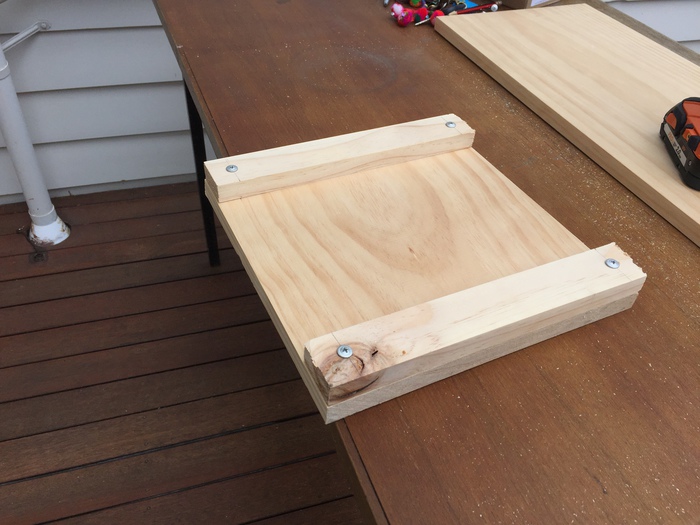
The base of the photo booth is pretty sturdy and heavy (in comparison to the sides). This definitely worked in my favour, as it kept the centre of gravity low. When we later add the screen and button to the front of the booth, we won’t be so worried about it being tipped over.
The above could be improved by countersinking the screws, but I’ll leave that decision up to you.
The Left and Right Side Walls
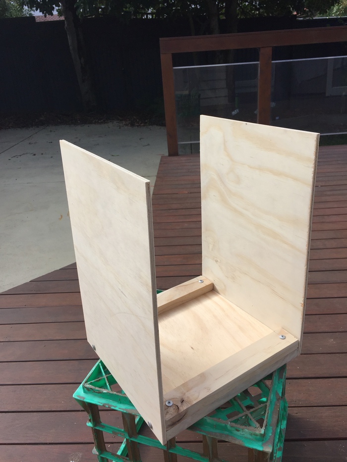
The side walls are cut, drilled, and attached to the base. Note that when pre-drilling your holes, you will want to leave plenty of space to attach your brackets (i.e. if you are following my exact design).
The metal brackets are, of course, optional.
The Brass Backets
If you follow the screenshots below, closely, you’ll note that I’ve been attaching some brass brackets to the build.
This improved the look and stability substantially.
There are six in total:
- Two at the base,
- Two at the top,
- Two to attach the flash diffuser.
The Front Panel
Ugh.
This was, without a doubt, the most painful part of the cabinet.
The cut-out for the screen
My suggestions are as follows;
- Trace the outline of the LED screen onto a piece of paper.
- Cut out the shape which you drew onto the paper, and position it onto the piece of wood that shall be the front of the photo booth.
- Try and center the piece of paper, exactly where the screen will be set
Ensure to keep;
- Sufficient room above the screen to mount the camera, and
- Sufficient room below to place the arcade button.
Once you have determined the correct position for the screen with the paper guide, trace the shape onto the wood to be cut out.
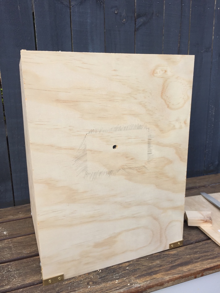
In the above screenshot I have already attached the front panel, but I would strongly recommend keeping the front panel detached, while drilling and cutting the required holes.
Once the shape has been sketched onto the panel, drill some holes to help you insert your saw of choice (i.e. a jigsaw), and complete the cut.
Check to see if the screen fits, by holding it up against the hole.
In my case, the hole was slightly too small.
I spent the next hour with a wood file, gradually increasing the size of the hole, until it fit exactly. The process was time consuming, however the end result was a perfect fit.
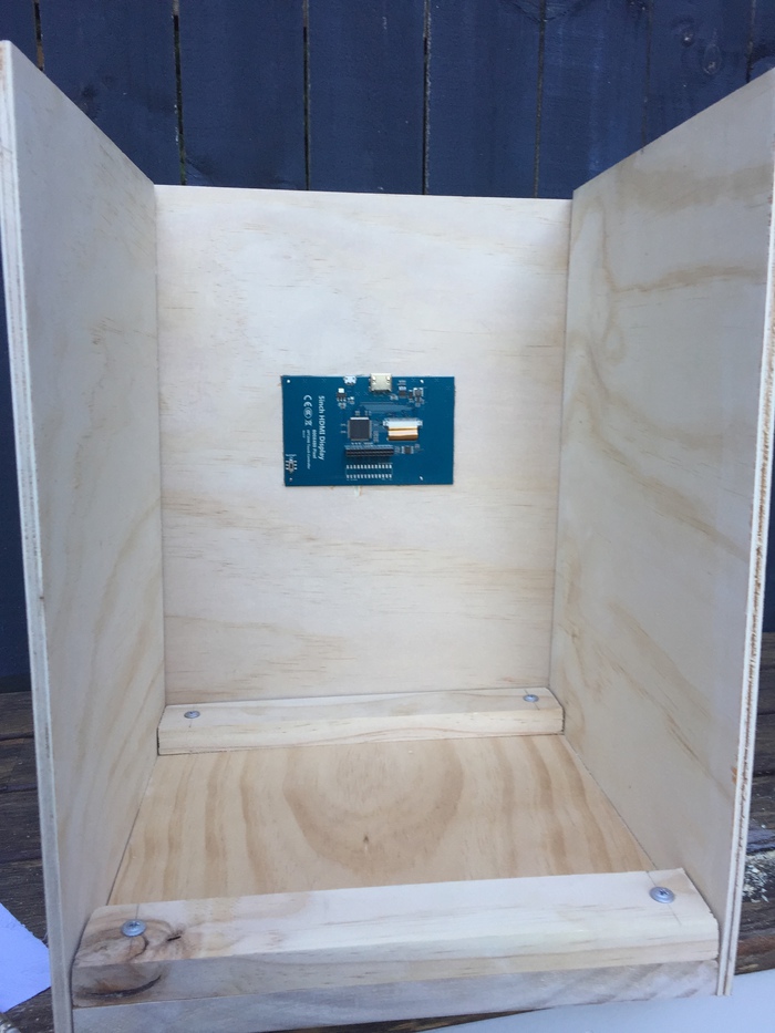
Drilling the Holes for the Button and Camera
I don’t have detailed instructions for this part, but essentially you just need to drill the holes for each component.
The button includes a threaded shaft, and plastic nut. It affixes to the front panel pretty easily.
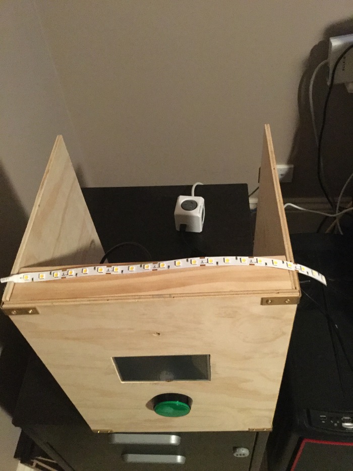
(the lights will get discussed in a future post).
The camera needs to be attached to the back of the panel, to line up with the hole you have drilled.
I managed to 3D print a small part that helped with this. This isn’t entirely necessary however, as I am sure you can come up with other methods for attaching this.
I’ve also attached my Raspberry Pi (inside it’s case) to the back of this panel, using double-sided tape.
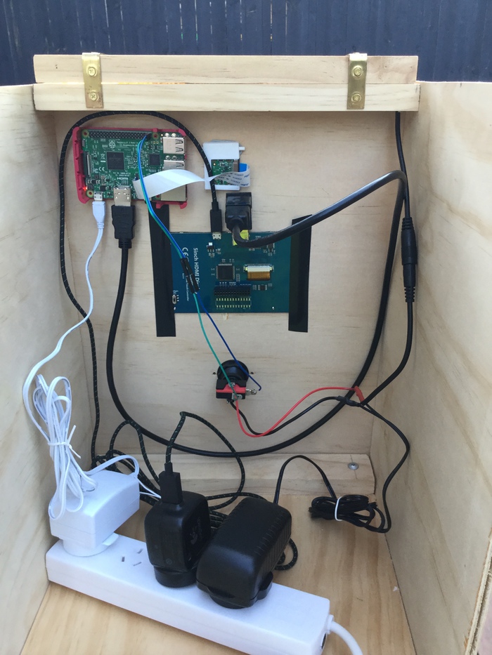
(I'll explain the lights and wiring shortly).
The Flash Diffuser
The final piece of wood that I cut was a “flash diffuser” (I will be discussing the LEDs in detail later).
However, when I was installing the lights, I found that “direct light” off of the LEDs felt a bit unpleasant.
By “hacking” a grooved angle into an additional piece of wood (off which the light would then bounce), the comfort was improved substantially.
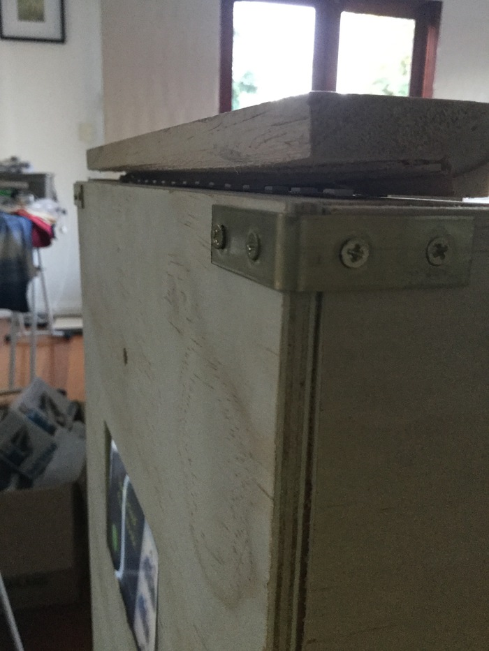
This completes the woodwork section of the build.
Next article
For the next article in this series, I’ll be talking about mounting the LED lights and connecting up the circuits.